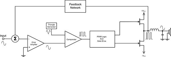
The Class D amplifier operates much like a switched mode power supply (Figure 1).
The key benefit of the Class D amplifier is its high efficiency of about 90%. This is much better than its closest analog rival, the Class AB amplifier, with an efficiency of 50 to 70%.
The Class D amplifier converts the input analog signal into a pulse width modulated (PWM) waveform. The PWM waveform drives the push-pull FET output stage fully on or off for each pulse. When one of the FETs is on, the current through it is high, but the voltage across it is very low, so power is only dissipated during the brief transitions between the on and off state. Likewise, when the FET is off, the voltage across it is high, but the current is near zero. Again, there is no power dissipation except in the state transitions.
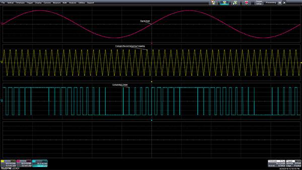
Conversion of the analog waveform into a PWM waveform is done by applying the analog waveform to one input of a comparator while a triangle or ramp waveform, at the desired switching frequency, is applied to the other input (Figure 2). The upper trace represents the input waveform, in this case a 10 kilohertz (kHz) sinewave, which is applied to one input of a comparator. The center trace is a 250 kHz triangle wave which is applied to the other comparator input. The output of the comparator is the PWM waveform shown in the lower trace. The pulse width varies with the amplitude of the input signal.
The output of the FET push-pull power stage is also a PWM signal. This is applied to a simple inductor-capacitor (L-C) low-pass filter to recover the amplified analog waveform. The frequency of the triangle wave has to be much higher than the corner frequency of the low-pass filter.
The gain of the Class D amplifier is affected by the bus voltages. While it has a poor power supply rejection ratio, it is corrected by using feedback around the amplifier. This is shown in the block diagram of Figure 1, where feedback is taken from the filter input.
The class-D Stereo Amplifier IC requires 10 VDC to 30 VDC power.
The VSP Amplifier Board uses the custom IC (MRXVSP2D).
The VSP Amplifier Board fully satisfies all the requirements of FMVSS#141.
Precision operation is assured by built in IC oscillator.
Vcc Power Input Pin is connected to nominal +12 VDC that has a Common Ground with the IC sound Input and Output as well as Control lines.
The two Digital Control Inputs control the four distinct dB levels of the D Class amplifier gain, as if required by the FMVSS #141.
(GAIN0 and GAIN1)